
Industrial Pump Specialists
Since 1979
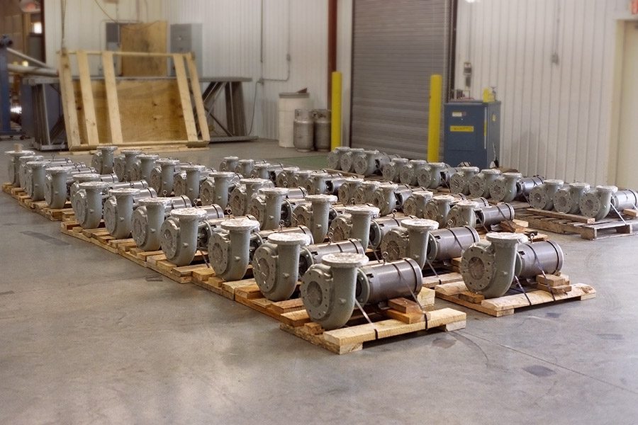
Vertiflo Pump Company, Inc. was established in 1979 to design, sell and build packaged lift stations. Since 1981, Vertiflo has concentrated on manufacturing industrial pumps including vertical process pumps, sump pumps, end suction pumps and self-priming pumps in cast iron, stainless steel and special alloys.
Vertiflo pumps are designed for industrial applications and currently over 30,000 are operating successfully worldwide. Vertiflo is recognized as a quality manufacturer of dependable pumps, and continues to grow and encompass new applications in the pump industry.
Need Help Finding the Perfect Pump?
Vertiflo’s online pump selection software can help determine the best pump for your industrial project.
North American Distributors
Use our pumps distributor locator to find a Vertiflo Pump distributor near you.